
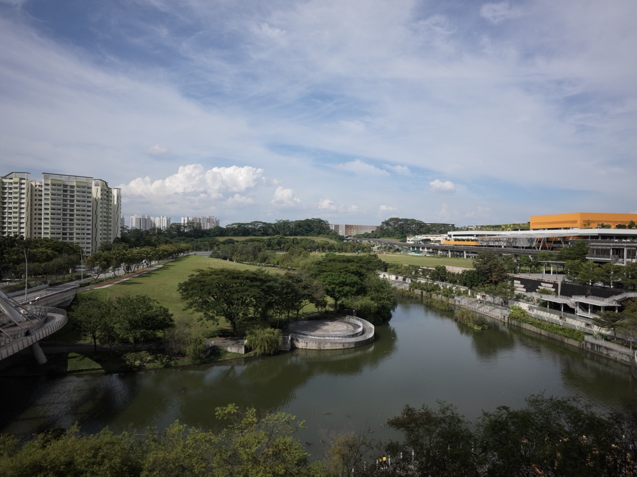
Hydraulic engineering explains why a pump, pipe network or drain can meet a local test and still fail the people it serves. Flow and pressure depend on the full physical route, its elevations, losses, controls and downstream conditions.
This guide follows hydraulic performance from required service and mass balance through pump selection, open-channel flow, model boundaries, as-built levels, maintenance and actual delivery. The gold standard is evidence that the endpoint works—not a large pump rating or a convincing computer simulation.
It is a specialist companion to Water Resources Engineering, Civil Engineering and Mechanical Engineering.
Quick answer: five parts of a trustworthy hydraulic system
- The required flow and pressure are defined where the service is needed.
- The complete hydraulic route, including elevation and losses, is evaluated.
- Pump or channel capacity is assessed under realistic operating conditions.
- Measurements and models explain their reference, uncertainty and limitations.
- An owner can detect deterioration and restore the intended service safely.
Follow the flow from source to user
1. The pump passed its test, but the farthest user received too little water
A water distribution project installs a pump advertised to deliver its specified duty. The acceptance test at the pump outlet appears satisfactory. At the farthest branch, however, the intended water supply remains inadequate at busy periods. The pump may be performing exactly as designed, while the distribution network is losing pressure through long pipe runs, fittings, elevation changes or interactions with other users. Hydraulic engineering begins at this distinction between equipment output and delivered service.
The discipline studies the movement and forces of fluids in pipes, pumps, channels, hydraulic structures and connected networks. It combines physical conservation principles, measurements, numerical models and practical knowledge of how equipment ages and operates. It is distinct from water-resources planning, which asks how much water may be available across a catchment, and from water-quality treatment, which asks whether that water meets requirements for its intended use.
The gold standard is not the largest available pump or deepest drain. It is a system whose flow, pressure, energy losses and operating boundaries have been assessed together; whose important measurements support the decision; and whose users receive the required service under the stated conditions. Technical excellence becomes meaningful when it appears at the right outlet, location and time.
2. Write the hydraulic duty before selecting the equipment
An engineering brief should specify where fluid starts, where it must end, the properties of the fluid and the range of conditions in between. Relevant requirements may concern flow, pressure, elevation, allowable fluctuations, energy use and the consequences of failure. A pipe network supplying intermittent irrigation presents different operating conditions from a building’s pressurised supply or a drainage channel responding to heavy rain.
Measurements and units need explicit meaning. A flow rate is a quantity per unit time, while pressure describes force per area; they cannot be compared or substituted casually. Nominal pipe diameter, velocity, level and head are related through the actual configuration, not through a single universal selection chart. A sales brochure can describe a component truthfully without defining whether that component fits the whole installation.
Begin with the critical endpoint or function. For a long distribution network, the farthest user or most demanding operating case may matter more than the average flow at the source. The duty should also state when the system may operate differently or not at all. A requirements document that says simply ‘adequate water pressure’ leaves a downstream dispute almost inevitable.
3. Mass conservation turns a network drawing into a reality check
Within a defined water network, the flows entering and leaving a junction must be reconciled with any change in storage, leakage or other relevant sources and sinks. For a simple steady, incompressible example without storage change, a junction receiving 30 litres per second and supplying branches carrying 12 and 13 litres per second has five litres per second unaccounted for in the simplified balance. That does not prove a leak by itself; the assumptions and measurements must first be checked.
Mass balance becomes more complicated when pumps start and stop, tanks fill, valves change position or demand varies. Engineers distinguish a temporary storage change from a permanent discrepancy. Meter accuracy, timestamps and the location of boundaries determine whether the account is meaningful. A confident spreadsheet can be wrong when one meter covers a different time period.
Real operational analysis should start with a clearly bounded diagram showing the flow pathways and relevant storage. The purpose is not to force every measurement to match an attractive sum. It is to identify what was observed, where the uncertainty lies and whether an unexplained difference deserves competent investigation.
4. Head and losses explain why a nominal pump flow is not a network guarantee
A pump adds energy to a fluid, but some of that energy is required to overcome elevation, resistance in pipes and fittings, and the conditions at the outlet. Pressure and head are connected quantities with defined units and fluid properties. The pump operating point emerges from the interaction of pump performance and the full system, rather than from one isolated nameplate value.
The route matters. Long, undersized or obstructed pipework may require more energy to transport a given flow. A valve selected without considering its actual duty can create unnecessary loss. An elevation change can materially change the required service. The engineer needs an appropriate network model and observations rather than assuming that installing a stronger motor will automatically produce the desired downstream condition.
The U.S. Department of Energy’s Pump Systems resources include guidance on matching pumps to requirements, examining piping losses, choosing appropriate equipment and evaluating performance. Those resources do not replace site-specific design rules, but they reinforce the system principle: review the pump and the connected hydraulic resistance together.
5. Open-channel flow behaves differently from a closed pressurised pipe
Water moving with a free surface in a canal or drain is influenced by channel geometry, slope, roughness, depth, obstructions and downstream boundary conditions. In a closed pressurised pipe, hydraulic behaviour and available pressure are described differently. A design method suitable for one cannot automatically be copied to the other.
Water level in an open channel may rise because the downstream condition restricts conveyance, even when rainfall-derived inflow has not increased. A bridge opening, sediment deposit or obstruction can affect water surfaces upstream. Conversely, enlarging a section locally can change flow behaviour elsewhere. The engineering team needs to understand the network rather than treat every drain as an independent empty box.
The U.S. Army Corps of Engineers’ HEC-RAS Hydraulic Reference Manual explains the underlying calculations used for one- and two-dimensional hydraulic analyses, including their assumptions. The availability of sophisticated modelling does not establish that the representation is correct without suitable site data and review.
6. Boundary conditions are where many tidy models become unreliable
A hydraulic model needs information about what enters, leaves or controls its domain. For a channel, this might include inflow variation and a downstream water-level relationship. For a pressurised network, it might involve reservoirs, pumps and user demand. When those conditions are wrong, numerical precision can create a false appearance of confidence.
Consider a hypothetical canal model that assumes the downstream outlet is freely discharging. During high tide, the actual receiving water level may restrict outflow and cause upstream depths to behave differently. A model can be calculated without error and still miss the physical event because it represented the wrong boundary. The same problem can arise with unrecognised control valve positions or a storage tank’s initial condition.
A strong hydraulic report states the design and assessment conditions, the observations supporting them, sensitivity to uncertainty and which cases were not evaluated. This is particularly important when a site lies near an approval or safety threshold. A visual colour map is not a substitute for a credible physical boundary.
7. The drawing of a drain is not its as-built capacity
Channel widths, bed levels, pipe slopes, inverts, outfalls and physical connections need accurate geometry. A design drawing describes the intended arrangement, while as-built verification establishes what was constructed. Even a small change at a controlling location can affect hydraulic performance or future maintenance.
Survey quality should reflect the decision. A drain’s actual invert is not reliably established by guessing from a road surface or copying a historical plan. Engineers may need a qualified survey, an appropriate vertical reference and a clear record of inaccessible areas. Where underground services intersect with drainage, the relevant records and safe investigation procedures are essential.
The Surveying Engineering and Geospatial Engineering guides explain why position and level require defined references. Hydraulic analysis needs that physical truth at the locations where flow is restricted or controlled.
8. Select pumps across the operating range, not one impressive point
Pump performance varies with operating conditions. The required flow may change between normal demand, peak periods and periods when one part of a network is unavailable. A pump sized only against a favourable single point may be inefficient or unsuitable during the conditions that matter most.
Selection should account for the real system curve and the permitted operating range, together with efficiency, availability, maintenance access, relevant vibration and other risks. Parallel or standby pumps need integration assessment; several identical units do not automatically create proportionate capacity. Control arrangements and shared supplies can impose limits that are invisible in a component quotation.
The Department of Energy’s Better Plants pumping guidance discusses matched pump selection, pipe and valve pressure loss, re-optimisation as requirements change and maintenance. Its emphasis on system efficiency is useful, but the project’s applicable safety and hydraulic design standards remain decisive.
9. Sediment and debris change the system people actually operate
A canal or drainage inlet may satisfy its original design assumptions while new sediment, debris or vegetation reduces effective capacity. Flow conditions then depart from the drawing. Maintenance records should track where and how these changes occur rather than assume that periodic visits automatically preserve the design.
Singapore PUB’s earth-control-measures guidance notes that silty construction runoff can accumulate in public drains and canals, diminishing their ability to convey stormwater and contributing to flood risk. The lesson links construction-site responsibility with downstream hydraulic performance.
Hydraulic design should make relevant inspection and access possible. It should also consider the source of recurring deposits and whether a control measure changes the problem rather than merely removing material for a short time. A drain kept clear by competent operation is part of the engineering system.
10. Check that drainage measures serve the whole catchment
A local drainage improvement can lower water levels at one location while changing conditions elsewhere. Upstream storage, channel conveyance, land levels and downstream receiving waters interact. Hydraulic assessment should examine the affected system boundary and the consequences for neighbouring developments.
Singapore PUB’s Code of Practice on Surface Water Drainage is the seventh edition from December 2018 with amendments through Addendum No. 3 in April 2025 as listed in October 2026. The associated guides address detention and managing runoff. Its actual application belongs to qualified professionals and the approving authorities; a general article cannot substitute for its prescribed design provisions.
The question is not simply whether a proposed pipe is larger. What is the intended flood or water-delivery outcome, what input and downstream scenarios were evaluated and who maintains the supporting elements? An engineer should be able to explain how the work affects the places beyond the project fence.
11. Instrumentation is only evidence when it represents the relevant flow
Flow meters, pressure sensors and level instruments help engineers understand hydraulic performance, but each measures in a particular location and under a defined principle. Sensor fouling, wrong installation, time lags or calibration issues can distort the picture. A steady pressure reading at the pump outlet may hide a problem at the farthest customer.
Monitoring design starts with the decision that needs to be made. Which signals would distinguish lower source availability from a restriction in the network? Does the reading correspond to a transient event or a representative steady condition? Are timestamps aligned across devices? The best system uses enough trustworthy measurements to identify meaningful changes without flooding operators with uninterpreted alarms.
An excellent control panel can still be wrong about what is happening physically. The Control Systems Engineering guide discusses the difference between a valid signal and a correct process outcome; hydraulic operations depend on applying that discipline to real water and fluid movement.
12. Maintenance and safe access determine real capacity over time
Pumps wear, filters obstruct, valves fail to move as expected and instruments drift. A network’s usable performance therefore changes over the asset’s life. Engineering cannot end with successful commissioning if the operator lacks drawings, spares, safe access and qualified support to preserve the service.
Maintenance should be informed by the known physical mechanisms and appropriate inspection methods. A repeated low-flow incident may reflect a recurring obstruction, poor valve arrangement or unsuitable pump operation. Replacing one unit without understanding the system may reproduce the same outcome. The team should document observed conditions and examine whether corrective work actually improved delivery.
Safe work around pressurised fluids, moving machinery and water infrastructure requires site-specific authorised practices. A public guide must not be mistaken for instructions to adjust hazardous equipment. Competent personnel need current system information, the required approvals and appropriate verification after work.
13. Hydraulic modelling must be tied to observations and limitations
Models can help explore flows, levels and alternatives across conditions that are difficult to observe simultaneously. Their value depends on appropriate geometry, roughness, flow inputs, boundary conditions and the computational approach. A very fine computational grid cannot compensate for an incorrect culvert elevation or a wrong downstream stage.
Model testing should include comparisons with relevant observed events when available, checks on mass balance, sensitivity analysis and examination of unexpected results. Where no suitable calibration events exist, that limitation belongs in the report. Engineers should distinguish a scenario result from a forecast guaranteed to occur, particularly when the model informs public risk decisions.
The HEC-RAS documentation portal provides hydraulic references and notes on software versions. A designer should record which tool and model configuration produced the result because changes in software, terrain or assumptions can affect later reproduction and review.
14. Hydraulic efficiency cannot replace the promised end service
Reducing pressure or pump energy may save money, but the benefit is not legitimate if a school, factory or irrigation user no longer receives the required water. Likewise, a drainage scheme that protects one car park while increasing exposure elsewhere needs further assessment before anyone declares it successful.
Use measures that represent the complete function: flow delivered at critical locations, required pressure or level, acceptable water availability, safe operation, energy use and response to disturbances. A component’s nominal efficiency and the actual system’s output are related but different metrics. The cost of maintenance, repairs and periods of lost service also matters to the long-term decision.
The gold standard of Hydraulic Engineering is a physical system whose performance can be explained from source to endpoint, measured honestly and maintained over time. It is successful when the useful fluid reaches the right place in the required condition—not when one device looks good on a test stand.
Worked scenario: the distribution pump passes, the last branch struggles
This is a fictional management case, not a real design assessment. A public facility commissions a pump and records satisfactory flow at a local test point. At peak demand, a remote branch has insufficient service. Engineers need to review measurement points, actual flow requirements, head losses, elevations, control positions, simultaneous demand and the scope of the acceptance test before attributing the fault to the pump.
| Evidence | What it establishes | What remains unknown |
|---|---|---|
| Pump performance test | Equipment worked at specified observed conditions | Flow at the critical remote user |
| Pipe installation drawings | Intended route and equipment were designed | Exact as-built geometry and current restrictions |
| One source flow meter | Flow passed a particular measurement boundary | Distribution among branches and storage change |
| Modelled head losses | Response predicted under stated assumptions | Whether assumptions match current demand and valves |
| Work order closed | A defined maintenance task was recorded | Whether endpoint delivery was restored and verified |
Questions to ask your hydraulic engineering team
- Where exactly must the fluid arrive, and what service requirements apply?
- Are flow, pressure, energy, elevation and their units distinguished correctly?
- Is the full pipe or channel route, including downstream conditions, represented?
- Are model assumptions and measurements traceable to the as-built configuration?
- Could sediment, fouling, leaks or controls explain changing performance?
- Have energy and cost improvements preserved required service at all critical users?
- Do maintenance and monitoring have owners who can act on real findings?
Official technical references and related eduKate articles
- US Army Corps of Engineers — HEC-RAS Hydraulic Reference Manual
- USACE — HEC-RAS Documentation and Model Guidance
- US Department of Energy — Pump System Efficiency and Selection
- Singapore PUB — Code of Practice on Surface Water Drainage (Addendum No. 3, April 2025)
- PUB — Earth Control Measures and Drainage Sedimentation
- eduKate — Water Resources Engineering
- eduKate — Surveying Engineering
- eduKate — Pump Output and Tail-End Delivery Case Study
- eduKate — Sectors and Services Directory
Hydraulic design, modelling, water-infrastructure operations and work on pressurised systems require site-specific data, authorised professionals and applicable safety and regulatory rules. This educational article is not a pump-setting, flood-design or drainage approval procedure. Return to the Gold Standard master hub.