
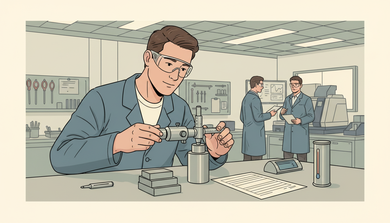
A certificate can show a metallic specimen exceeded a tensile requirement while leaving unanswered whether it represented the installed part. Materials testing matters when engineers can trace a result from a real specimen to the decision that depends on it.
The Gold Standard of Industrial Materials Testing explains specimen selection, mechanical properties, uncertainty, test-method standards and the limits of extrapolating from a laboratory result to service conditions.
The guide gives fictional tensile stress, elastic modulus and batch-strength calculations and uses current ISO and ASTM references. It is educational, not an approved test procedure or certification for any real part.
Chapter index
Scope, specimens and tensile mechanics · Chapters 1–13
- Materials testing connects a specimen to an engineering decision
- Start with the material and its service duty
- Distinguish testing, inspection and certification
- Identify the actual lot and sampling frame
- Preserve specimen orientation and location
- Use the right edition of the standard
- The tensile specimen must have controlled geometry
- Engineering stress uses original cross-sectional area
- Worked example: engineering stress from a tensile load
- Engineering strain uses the defined initial gauge length
- Worked example: a small-strain modulus estimate
- Yield and tensile strength answer different questions
- Elongation and reduction of area describe ductility
Hardness, impact, fatigue and metrology · Chapters 14–26
- Fracture location is part of the test record
- Hardness is not a direct replacement for tensile strength
- Vickers hardness depends on an accurately read indentation
- Rockwell results require the declared scale
- Impact tests examine behaviour under a defined dynamic event
- Temperature changes mechanical properties
- Repeated loads introduce fatigue risk
- Creep and stress relaxation involve time
- Microstructure helps explain but not replace property tests
- Non-destructive inspection answers a different question
- Surface condition and preparation influence results
- Calibration and traceability give measurements context
- Uncertainty and tolerance should not be confused
Sampling, results, audit and connected subjects · Chapters 27–36
- Worked example: mean and spread in a fictional batch
- Acceptance sampling requires a defensible population
- A pass-fail count needs its denominator and severity
- Failure analysis is a multidisciplinary process
- Separate material conformity from product design adequacy
- Supplier reports need independent verification where risk justifies it
- Keep a complete reproducible test record
- Audit a material property from specimen to decision
- Frequently asked questions about industrial materials testing
- Continue through the Gold Standard engineering subjects
Quick comparison: what a test can establish
| Test | What it measures | What it cannot alone establish |
|---|---|---|
| Tensile | Strength and deformation under stated conditions | Full component reliability |
| Hardness | Defined indentation resistance | Universal tensile strength |
| Charpy | Absorbed impact energy in a defined specimen | Universal fracture toughness |
| Inspection | Indications within method capability | Absence of every flaw |
1. Materials testing connects a specimen to an engineering decision
Industrial materials testing examines how a defined material or specimen behaves under stated loading, environmental or inspection conditions. It supports manufacturing quality, design, supplier acceptance and failure investigation. A measured strength or hardness is evidence about the specimen and method—not an unconditional guarantee about every component made from the same material.
The gold standard starts by identifying the decision, the applicable material specification, the sampling population and the property that matters. A laboratory number is only defensible when the specimen, test conditions, uncertainty and report can be independently traced.
2. Start with the material and its service duty
Steel, aluminium, polymer, composite and ceramic products experience different failure mechanisms. An automotive bracket under repeated loading, a pressure component, a food-contact package and an architectural fastener do not require identical testing programmes. Service temperature and environment may be as important as initial strength.
Define expected duty, consequence of failure, acceptance criteria and authorised standards before buying laboratory tests. More measurements are not necessarily better if they answer a question the engineer does not need.
3. Distinguish testing, inspection and certification
Testing applies a defined method to obtain a property or result. Inspection evaluates a product against specific requirements and may include examination or measurement. Certification and conformity assessment have particular rules about responsibility and evidence.
A certificate from one test laboratory does not automatically certify the whole factory, every shipment or an entire structure. Ask exactly which specimens, test methods and conclusions a document covers.
4. Identify the actual lot and sampling frame
Materials can vary between heats, batches, production lines and locations within a large part. Testing one convenient specimen may not represent the entire delivery. Sampling rules belong to the relevant contract, product standard or approved plan.
Keep unique lot, specimen and position identifiers. A perfect test performed on a sample that cannot be linked to the supplied material gives weak assurance for the purchase decision.
5. Preserve specimen orientation and location
Rolled, forged, welded, cast and additively manufactured materials may have direction-dependent properties. A longitudinal specimen can give different results from a transverse specimen, and a weld region may behave differently from unaffected base metal.
Record extraction orientation, gauge section, process history and condition. Do not compare results across orientations as though they were repeated observations of one identical material state.
6. Use the right edition of the standard
Test procedures change through revisions. As of October 2026, ISO 6892-1:2019 specifies room-temperature tensile testing of metallic materials and was confirmed in 2025. ASTM E8/E8M-24 is a current US method for tension tests.
The method specified by a customer, regulation or engineering drawing governs a real acceptance programme. Similar titles do not make standards technically interchangeable, and results produced under different editions need a justified comparison.
7. The tensile specimen must have controlled geometry
Uniaxial tensile tests depend on specimen cross-section, gauge length, alignment and preparation. A poor transition or surface defect can trigger fracture unrelated to the intended representative material behaviour.
Inspect and record dimensions before testing, using suitable calibrated equipment. The actual geometries prescribed by a standard must be followed; an educational diagram is not a substitute for laboratory instructions.
8. Engineering stress uses original cross-sectional area
In a conventional engineering stress calculation, axial load is divided by the original specimen cross-sectional area, with clearly stated units. This differs from true stress, which considers the current area under a different model.
Keep load and area provenance. A data-acquisition channel displaying newtons and a report using megapascals must have the correct conversion. A precise stress-strain curve cannot rescue a mistaken specimen diameter.
9. Worked example: engineering stress from a tensile load
Suppose a fictional metallic specimen has original cross-sectional area 50 mm² and is under 10,000 N axial force. Engineering stress is 10,000 ÷ 50 = 200 N/mm², equivalent to 200 MPa. The result assumes the load is appropriately axial and the original area is correct.
This calculation does not prove yield, maximum strength or component safety. Those require the correct stage of the stress-strain curve and a product-specific engineering judgement.
10. Engineering strain uses the defined initial gauge length
Engineering strain is change in gauge length divided by the original gauge length. It is dimensionless, often reported as a decimal or percentage. Different extensometer configurations and gauge conventions can affect what the measurement represents.
A reported deformation of the whole test frame is not automatically the specimen’s gauge strain. Machine compliance, gripping and sensor placement require appropriate treatment.
11. Worked example: a small-strain modulus estimate
A fictional test records an extension of 0.05 mm over a 50 mm original gauge length while nominal stress is 200 MPa. Engineering strain is 0.05 ÷ 50 = 0.001. If this point lies within a verified linear elastic region, illustrative modulus estimate is 200 MPa ÷ 0.001 = 200,000 MPa, or 200 GPa.
One point is not sufficient for a robust modulus fit. The linear region, sensor calibration, data noise and testing method need evaluation. This is an educational calculation, not a certified modulus for a particular alloy.
12. Yield and tensile strength answer different questions
Yield behaviour concerns onset of significant permanent deformation under the applicable definition. Ultimate tensile strength is the largest engineering stress reached on the recorded tensile curve. Different materials may show continuous yielding, discontinuous yielding or other behaviour.
State the method used to determine yield or proof strength rather than selecting a convenient visually apparent point. High tensile strength by itself does not establish ductility, toughness or fatigue durability.
13. Elongation and reduction of area describe ductility
Elongation and reduction of area provide complementary measures of deformation observed through tensile testing. Their interpretation depends on specimen dimensions, fracture location, material condition and test method.
Two materials with similar strength can fail differently after yield. Ductility results should not be copied across products without checking geometry and processing history. A single percentage cannot describe every fracture mechanism.
14. Fracture location is part of the test record
A tensile specimen may fracture within the expected gauge section or near a grip or specimen defect. The location can affect interpretation and whether certain results are valid under the specified method.
Document fracture position and any anomalies. A large breaking force from a specimen that failed because of a grip-related defect must not be silently included as an ordinary material-property result.
15. Hardness is not a direct replacement for tensile strength
Hardness tests measure a resistance to defined indentation or other response under an established method. Some material families show empirical relationships between hardness and strength, but these are not universal conversions.
Use hardness for the property and product question it can actually support. A hard surface may coexist with a brittle substrate, and a coating result may say little about the underlying bulk material.
16. Vickers hardness depends on an accurately read indentation
ISO 6507-1:2023 covers Vickers hardness testing of metallic materials and defined indentation-diagonal ranges. Surface preparation, indentation spacing and measurement of the diagonals influence the result.
Small impressions can have substantial relative measurement uncertainty. Record test force, indenter, location and method. Do not claim a microscopic indentation automatically characterises the entire thickness of a part.
17. Rockwell results require the declared scale
ASTM E18-25 specifies Rockwell and superficial Rockwell hardness test methods. A reported number without its scale and test conditions can be ambiguous or misleading.
Different scales employ different test conditions. Do not compare HRB and HRC numbers numerically as though they were on one continuous ruler. Validate the instrument and method for the actual material range.
18. Impact tests examine behaviour under a defined dynamic event
Charpy tests measure energy absorbed by a notched specimen under specified impact conditions. They can help characterise material behaviour relevant to temperature, notch sensitivity and transitions but are not identical to full fracture-toughness assessments.
ISO 148-1:2016 remains the published method as of October 2026 while a replacement final draft is under development. Always check the operative version at the time of the test.
19. Temperature changes mechanical properties
Strength, ductility, toughness and time-dependent behaviour can change with temperature. Room-temperature results may not adequately represent hot service, cold environments or a component exposed to thermal cycles.
Choose appropriately specified test temperatures and document temperature control. Never assume a material that passed one tensile test can safely operate at any temperature.
20. Repeated loads introduce fatigue risk
A component may fail under cyclic loading even when the peak stress is below one-time tensile strength. Fatigue assessment depends on cycle count, mean stress, stress concentrations, surface condition, environment and material variability.
Laboratory fatigue data must be matched to the relevant design method. A single nominal endurance number should not be used as a guarantee for an arbitrary geometry or welded detail.
21. Creep and stress relaxation involve time
At suitable stress and temperature, some materials exhibit time-dependent strain or loss of stress under constrained conditions. A short test cannot establish long-term behaviour without a validated model and supporting evidence.
Define intended lifetime and relevant temperature, then select suitable testing and engineering evaluation. An apparent lack of immediate deformation does not demonstrate that an elevated-temperature part is safe for years.
22. Microstructure helps explain but not replace property tests
Grain structure, phase distribution, porosity and inclusions influence how materials behave. Microscopy and other examination techniques can reveal useful features, but a beautiful image is not an automatic strength or reliability measurement.
Connect microstructural observations to the specific processing history and test outcomes. Avoid identifying every visible feature from one low-resolution picture without qualified interpretation.
23. Non-destructive inspection answers a different question
Ultrasonic, radiographic, magnetic, penetrant and visual methods may detect defined discontinuities without destroying the inspected component, under appropriate conditions. Detection capability depends on equipment, procedure, geometry and operator competence.
A clean inspection result does not prove that no flaw exists anywhere. State which defect types and sizes the method was qualified to detect, and what regions were covered. Physical-property and flaw-detection evidence complement each other.
24. Surface condition and preparation influence results
Machining, polishing, residual stress, decarburisation, corrosion and coatings can affect a test specimen. Preparation chosen for convenience can alter the property being measured, particularly in small or surface-sensitive specimens.
Document preparation and storage conditions. A difference between two laboratories may reflect preparation or specimen location rather than the test machine alone.
25. Calibration and traceability give measurements context
Force transducers, extensometers, temperature instruments and dimension gauges need evidence of suitable calibration and verification. Metrological traceability documents a chain to references with associated uncertainty; it does not by itself guarantee the test was appropriate.
Link measuring instruments to the specimen, date, method and report. ISO/IEC 17025:2017 sets requirements for competent, impartial and consistent testing laboratory operation.
26. Uncertainty and tolerance should not be confused
Measurement uncertainty describes the dispersion or limits associated with a measured quantity under an uncertainty model; engineering tolerances identify acceptance boundaries. A measured number near a limit may require a declared decision rule.
Describe relevant uncertainties and whether the acceptance decision guards against false acceptance or false rejection. Avoid presenting digits that exceed the measurement method’s meaningful precision.
27. Worked example: mean and spread in a fictional batch
A fictional lab measures tensile strengths of five sampled coupons as 598, 604, 601, 597 and 600 MPa. Arithmetic mean is (598 + 604 + 601 + 597 + 600) ÷ 5 = 600 MPa. The observed minimum is 597 MPa and maximum is 604 MPa, a range of 7 MPa.
That mean does not establish that every component or every production lot meets a required limit. Sampling, measurement uncertainty, the lower tail and the applicable product standard determine what decision the data can support.
28. Acceptance sampling requires a defensible population
Selecting five coupons from one edge of a plate may not represent the centre or other production batches. A credible sampling plan states where specimens came from and what population the conclusions cover.
Do not extrapolate a pass from an unrepresentative sample to all future shipments. Describe the contractual acceptance rule and whether destructive testing changes the tested item’s later use.
29. A pass-fail count needs its denominator and severity
Suppose a fictional incoming batch contains 80 tested specimens, of which 76 meet the complete specified criteria and 4 do not. The observed pass fraction is 76 ÷ 80 = 95%; it does not mean the factory is ‘95% safe’.
Different failed properties may have very different consequences. Investigate the four failures by test type, lot and root cause before deciding on disposition. Do not average a critical failure into an otherwise attractive quality score.
30. Failure analysis is a multidisciplinary process
After a component fails, combine operating history, loading, environment, material records, fracture examination and relevant testing. A post-failure hardness result alone may not identify the initiating cause.
Preserve physical evidence and differentiate observation from inference. The question is how competing hypotheses fit all available evidence, including manufacturing and service conditions, not which narrative sounds dramatic.
31. Separate material conformity from product design adequacy
A component can be made from fully conforming material yet fail because of poor geometry, assembly, overload or an unsuitable environment. Likewise, superior material properties cannot compensate for a fundamentally flawed system design.
Report what materials testing established and which structural or operational questions remain unresolved. Do not label one passed coupon a certification of the complete machine or building.
32. Supplier reports need independent verification where risk justifies it
Certificates of analysis and inspection records can be useful, but a purchaser must confirm the document refers to the supplied lot and was generated by a competent process. Risk and contract determine when witness tests or independent audits are justified.
Keep sample chain of custody, instrument references, batch identity and reported exceptions. A reputable supplier’s logo cannot replace correct traceability for an individual shipment.
33. Keep a complete reproducible test record
The report should preserve specimen identity, geometry, location, method and edition, instruments, environmental conditions, raw or suitable original readings, results, uncertainty where required, deviations and responsible approvals.
Another qualified reviewer should be able to reconstruct important calculations. A final number without its source is weak evidence, especially when challenged during a failure investigation.
34. Audit a material property from specimen to decision
Select one claimed property and trace it from design requirement through material identity, sample plan, preparation, calibrated testing, data reduction, decision rule and end-product use. Check that every stage has a responsible owner.
Then change one plausible condition: a different orientation, a lower temperature or a new supplier lot. Identify which test assumptions would need reassessment. That is a better gold-standard lesson than memorising a specimen’s record strength.
35. Frequently asked questions about industrial materials testing
Does a tensile-test pass prove a whole part will never fail? No. Is hardness the same as tensile strength? No. Can Charpy energy be used as a universal fracture-toughness figure? No. Does a polished specimen automatically represent a finished weld? No.
Must every product use the same standard? No. Do more decimal places imply better test quality? No. Can an accredited lab guarantee that sampling was representative? Not without a justified sampling and acceptance scope.
36. Continue through the Gold Standard engineering subjects
Connect this guide to Instrumentation Engineering, Industrial Maintenance, Industrial Tribology, Information Quality and Engineering.
Primary references are ISO 6892-1:2019, ASTM E8/E8M-24, ISO 6507-1:2023, ASTM E18-25, ISO 148-1:2016 and ISO/IEC 17025:2017. All calculations and specimen data in this guide are fictional.